UncertainJ
Well-Known Member
- Messages
- 2
- Reaction score
- 0
- Points
- 45
- Boat Make
- Yamaha
- Year
- 1999
- Boat Model
- LS
- Boat Length
- 20
LS2000 Fuel Air Separator Installation Instructions (Yes..I used ChatGPT to help list these instructions)
Parts Required
- Edelbrock 2.5–3.0 PSI electric fuel pump
- MicroGard 33591 fuel filter (air separator)
- Assorted brass tees and hose fittings
- Fuel hose (1/4" and 5/16" as needed)
- Inline fuse holder and fuse
- Wiring and terminals
- EVIL ENERGY 1/4" check valves or equivalent low-cracking-pressure fuel check valves
Fuel System Layout
Fuel Tank → Tee → Edelbrock Pump → Air Separator → Tee → EnginesEngine Return → Fuel Tank
Air Separator Return → Restriction → Engine Return Line
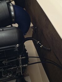
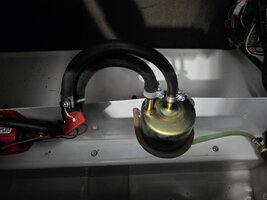
Air Separator Installation
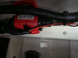
- Mount the MicroGard 33591 in a vertical position. A U-bolt, strap, or similar mounting bracket can be used to secure the filter.
- The MicroGard 33591 is a fuel filter commonly listed for early-2000s Ford Rangers and can be purchased from O'Reilly Auto Parts and most other auto parts stores. I chose to use this filter as the air separator because the original Group K separator is difficult to find, while the MicroGard filter is inexpensive, readily available, and has a large capacity with an inlet, outlet, and return port already incorporated into a single unit. When mounted in the proper orientation, it functions as both the fuel filter and air separator. One filter/separator is sufficient to supply both engines; there is no need to install a separate filter for each engine.
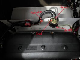
- The orientation of the filter is important. Mount it vertically with the return port positioned at the top of the filter. This allows trapped air to rise into the separator and be returned to the fuel tank through the return line.
- Connect the outlet of the Edelbrock pump to the inlet of the separator.
- Connect the separator outlet to a tee feeding both engines.
- Connect the separator return port into one of the engine return lines using a tee fitting.
- A restriction should be added to the separator return line so excessive fuel does not bypass the engine supply. The restriction does not need to be exact; it only needs to allow trapped air to purge while limiting fuel flow through the separator return. A carburetor jet installed in the hose or a small fuel shutoff valve (like the adjustable valve used in my setup) both work well for this purpose.
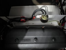
Fuel Pump Installation
- Mount the Edelbrock pump near the fuel tank, close to both tank supply lines and the air separator.
- Use a tee fitting to combine the two factory fuel tank supply lines into a single line feeding the pump inlet.
- Connect the pump outlet to the air separator inlet.
- Wire the pump through:
- Ignition-switched power or a dedicated dash switch
- Inline fuse
- Verify pump operation before starting the engines.
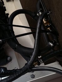
Return Line Setup
- Retain the factory return lines from both engines.
- Connect the air separator return line into either engine return line using a tee fitting. This allows trapped air and excess fuel from the separator to return to the tank through the factory return system.
- Install EVIL ENERGY 1/4" aluminum check valves, or an equivalent 1/4" fuel check valve with a very low cracking pressure (approximately 1–2 PSI or less), in both engine return lines:
- Make sure the check valves are installed with the flow direction pointing toward the fuel tank.
- The check valves should have a very low cracking pressure so they do not restrict normal return flow from the engines.
- On the engine return line that contains the air separator return tee, install the check valve between the engine and the separator return tee. This allows fuel from the separator to continue flowing toward the tank while preventing fuel from draining backward through the engine return circuit.
- On the other engine return line, install the check valve anywhere between the engine and the fuel tank.
Do not install check valves in the main fuel supply line.
Notes and Recommendations
- Use quality fuel hose and properly sized fuel injection or marine-grade hose clamps throughout the installation.
- After installation, run the fuel pump and thoroughly inspect the entire system for leaks before operating the boat. Check all fittings, tees, hose connections, the air separator, fuel pump, and carburetors.
- The Edelbrock 2.5–3.0 PSI pump will not over-pressurize the fuel system. The LS2000 uses a return-style fuel system, allowing excess fuel and air to return to the tank. In addition, Mikuni carburetor needle and seat assemblies typically require substantially more pressure than the pump produces before they are forced open.
- This modification is intended to improve fuel delivery, fuel retention, starting performance, and throttle response. It is not intended to compensate for carburetors that require rebuilding or cleaning.
- For best results, the carburetors should already be in good working condition with clean internal passages, proper pop-off pressure, and correctly functioning needles and seats.
- If the carburetors have clogged circuits, internal contamination, leaking needle and seats, deteriorated diaphragms, or other mechanical issues, those problems should be corrected before performing this modification.
- As with any fuel system modification, periodically inspect all fuel lines, clamps, fittings, and components for leaks or deterioration.
Results
After installation, the system should:- Improve cold starts
- Reduce fuel drain-back
- Improve idle-to-WOT throttle response
- Eliminate hesitation during hard turns
- Maintain continuous fuel circulation through the carburetors
Disclaimer
This is simply the setup that worked well on my 1999 LS2000. I am obviously not affiliated with Group K, Yamaha, or any of the manufacturers mentioned. Use this information at your own discretion, verify all fuel system connections for leaks, and make any modifications at your own risk.Hope this is helpful !
") Any feedback is welcome, thanks.
Any feedback is welcome, thanks.