• Welcome to Jetboaters.net!

    We are delighted you have found your way to the best Jet Boaters Forum on the internet! Please consider Signing Up so that you can enjoy all the features and offers on the forum. We have members with boats from all the major manufacturers including Yamaha, Seadoo, Scarab and Chaparral. We don't email you SPAM, and the site is totally non-commercial. So what's to lose? IT IS FREE!

    Membership allows you to ask questions (no matter how mundane), meet up with other jet boaters, see full images (not just thumbnails), browse the member map and qualifies you for members only discounts offered by vendors who run specials for our members only! (It also gets rid of this banner!)

    free hit counter

Low Voltage / Engine Fault / NOCO Install 2026 252SD

Thanks. Is there any chance you have a picture of that switch installed?
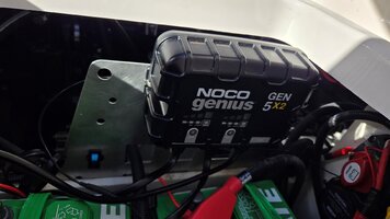
Pardon the poor heat shrink application. Mounted to some scrap aluminum I had laying around.

NOCO1.jpg

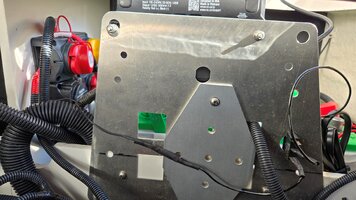
NOCO2.jpg
 
i'm also not in the ice belt like whiskydan...leave my batteries in the boat all season and the onboard charger hasn't left the boat.
not sure how your newer boat differ's from dan's or mine, but in his charger pic, the panel to the right is removable (see the aluminum angle?). it' carpet wrapped plywood and just blocks view, or keeps things from rolling forward into the gunwhale. mounted my noco to that panel. it is out of the way and leaves room for a small tote next to my batteries.
i'll post a pic later
I'll check that space more closely on my boat when I go back out. My battery is in the engine compartment, so the only thing in that space right now is the battery switch panel. And my NOCO that is lying on the deck until I mount it. I wonder why your and @WiskyDan battery is in that space? For the XDs, they might have the ballast in the way. But what's in that spot in the ARs?
 
we have the older 24' hull, they re-shaped the storage/engine compartments i think the older x models also had ballast in the way a bit, but still had batteries there.
 
I want to install my Victron shunt. I’m having trouble finding some good instructions to install it so it will read both my batteries. Every video on YouTube has other setups and I can’t find a good thread on this forum….although I thought I had a few months ago when I wasn’t planning to get one of these. Does anyone have a good resource?
 
I want to install my Victron shunt. I’m having trouble finding some good instructions to install it so it will read both my batteries. Every video on YouTube has other setups and I can’t find a good thread on this forum….although I thought I had a few months ago when I wasn’t planning to get one of these. Does anyone have a good resource?
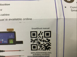
What is your question? How to hook it up? Use that QR code..

IMG_1350.jpeg
 
Update on my progress. I DMed @FSH 210 Sport earlier about some of this...thanks for the help.
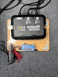
I drilled NOCO onto a bamboo board. If it ends up taking up too much room, I can always mount it to the side, but I like the idea of not putting extra holes in the boat.

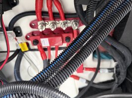
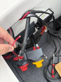
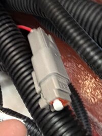
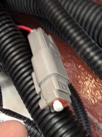
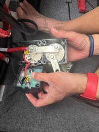
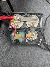
While trying to make the DVSR modification, I had to take the most left of those four vertical wires off (see first picture) to create slack to pull of the batter switch compartment. I had to use a wrench to get that nut off because my ratchet set wasn't deep enough to get past the length of the bolt. After getting it off, I somehow yanked a small red wire out of Deutsch connection (pictures 2 and 3).

I was not able to trace the wire back because it was tied off with a bunch of other looms and I didn't want to cut the tape. I will try harder tomorrow. Part of me wants to go buy a replacement Deutsch plug. But part of me is thinking about just using a butt connector and if the boat shop ever needs that connector to unplug it, he can add that back for me much faster and easier than I can.

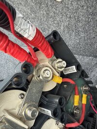
Doing research online, it MIGHT be connected to the bilge pump. The fourth and fifth pictures have a better picture of where that end went into the battery switch casing (house battery).

I did get the DVSR wire cut and crimped/heat shrinked to a ring connector. My only worry is if I got it crimped in there good enough. I used a lighter to heat shrink it.

Does anyone happen to know what that wire goes to already, or have any suggestions on going with the Deutsch or just using a butt until I have a need to disconnect it? I guess Yamaha wanted that to have an easy disconnect for a reason.
 

Attachments

  • IMG_8551.jpeg
    IMG_8551.jpeg
    3.8 MB · Views: 7
  • Coming from Batter Switch.jpeg
    Coming from Batter Switch.jpeg
    1 MB · Views: 4
  • Engine Compartment Just Behind Comaprtment Wall.jpeg
    Engine Compartment Just Behind Comaprtment Wall.jpeg
    590.3 KB · Views: 4
  • Engine Compartment Just Behind Comaprtment Wall.jpeg
    Engine Compartment Just Behind Comaprtment Wall.jpeg
    590.3 KB · Views: 5
  • Back of House Portion of Batter Switch Compartment.jpeg
    Back of House Portion of Batter Switch Compartment.jpeg
    2 MB · Views: 9
What is your question? How to hook it up? Use that QR code..

View attachment 245595
I've looked at it. I still am a little uncertain. Does this sound correct?

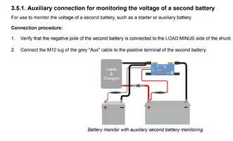
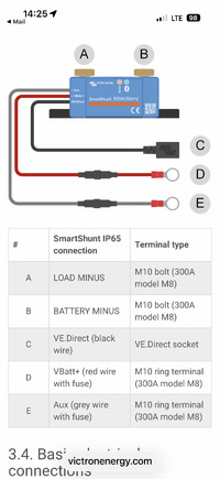
Connect a cable from House Negative to BATTERY MINUS with nothing else, including the NOCO. Everything else that was on the house battery negative terminal goes to LOAD MINUS, including the NOCO.
Then I use the attached picture to connect the Aux and VBatt+ wires on top of whatever else is already on the Start and House Battery positive terminals. Does this sound right?

Where are you all keeping your shunt? I was going to put it in the same compartment with my battery switches and NOCO. But it will be difficult to route all the cables to LOAD MINUS if it is not in the engine compartment next to the batteries.

Is it important to have a tool to meausre the torque.

Manual - SmartShunt IP65 Battery monitor
 

Attachments

  • VICTRON Aux Hookup.png
    VICTRON Aux Hookup.png
    201.7 KB · Views: 4
Last edited:
I've looked at it. I still am a little uncertain. Does this sound correct?

Connect a cable from House Negative to BATTERY MINUS with nothing else, including the NOCO. Everything else that was on the house battery negative terminal goes to LOAD MINUS, including the NOCO.
Then I use the attached picture to connect the Aux and VBatt+ wires on top of whatever else is already on the Start and House Battery positive terminals. Does this sound right?

Where are you all keeping your shunt? I was going to put it in the same compartment with my battery switches and NOCO. But it will be difficult to route all the cables to LOAD MINUS if it is not in the engine compartment next to the batteries.

Is it important to have a tool to meausre the torque.

Manual - SmartShunt IP65 Battery monitor
Correct.

the B connection goes to your house battery negative or battery minus

All the other negatives that were on the house battery go on the A terminal or system minus including the charger ground

IMG_0893.png

The red wire goes to the positive side of your house battery.

The grey wire goes to the positive side of your start battery.
 
Update on my progress. I DMed @FSH 210 Sport earlier about some of this...thanks for the help.
I drilled NOCO onto a bamboo board. If it ends up taking up too much room, I can always mount it to the side, but I like the idea of not putting extra holes in the boat.

While trying to make the DVSR modification, I had to take the most left of those four vertical wires off (see first picture) to create slack to pull of the batter switch compartment. I had to use a wrench to get that nut off because my ratchet set wasn't deep enough to get past the length of the bolt. After getting it off, I somehow yanked a small red wire out of Deutsch connection (pictures 2 and 3).

I was not able to trace the wire back because it was tied off with a bunch of other looms and I didn't want to cut the tape. I will try harder tomorrow. Part of me wants to go buy a replacement Deutsch plug. But part of me is thinking about just using a butt connector and if the boat shop ever needs that connector to unplug it, he can add that back for me much faster and easier than I can.

Doing research online, it MIGHT be connected to the bilge pump. The fourth and fifth pictures have a better picture of where that end went into the battery switch casing (house battery).

I did get the DVSR wire cut and crimped/heat shrinked to a ring connector. My only worry is if I got it crimped in there good enough. I used a lighter to heat shrink it.

Does anyone happen to know what that wire goes to already, or have any suggestions on going with the Deutsch or just using a butt until I have a need to disconnect it? I guess Yamaha wanted that to have an easy disconnect for a reason.
Any particular reason you didn't go with the negative wire cut and a switch that I mentioned? No need to remove the DVSR from the wall panel.
 
Any particular reason you didn't go with the negative wire cut and a switch that I mentioned? No need to remove the DVSR from the wall panel.
Why put a switch in that you need to turn on and off. The way he did it is automatic. To do the job correctly does not take that much time
 
Any particular reason you didn't go with the negative wire cut and a switch that I mentioned? No need to remove the DVSR from the wall panel.
I already was heading down the road of cutting that wire when you posted that. And then when you started talking about low resistance, my brain started thinking this will be beyond the scope of what I can do, or what I want to learn to do. And someone else had posted something (I think in a different thread) where they had done something with a wire behind the DVSR and it seemed to take a lot of work to route it around. That might have had more to do with where their batteries were located, though.
Also, I liked the idea of the permanent solution where I don't have to flip a switch. The method I did is even in their instruction manual, so it felt like a safe option. Also, anything that has do with cutting more holes (to mount the switch) scares me.
However, now that I have gone through that, I quite possibly would go with your option. Dealing with that tiny wire in such a tight space was a pain. I'm going to post a more thorough wrap-up of what I did, which will show my difficulties.
 
Why put a switch in that you need to turn on and off. The way he did it is automatic. To do the job correctly does not take that much time
Well.....then I did not do it correctly, ha ha. It took me waay longer than it should have. But I'd be able to do it much quicker if I had to again....although I now like the idea of not dealing with that tiny wire in that tiny space.
 
NOCO installed with DVSR mod. I ran into several rookie mistakes. Even though you can see most of what I did if you read through this thread, here it is compiled, with simple instructions for those who are as handyman illiterate as I am. I'll to answer very elementary topics that I had questions about. I’m not claiming what I did is the best way, it’s just the way I did it, and so far it seems to be working.

I have two batteries and bought a NOCO GENPRO10X2 so that each battery can be charged separately. I’ve had two seemingly random electrical faults, one manifested as an engine issue, since I got the boat seven months ago. It doesn’t take much reading on this forum to learn there is a consensus that these issues are solved by buying a battery charger.

Hooking up the charger is pretty easy. Connect the red to red and black to black. Then there is a matter of mounting it. I took an idea from @WiskyDan to mount it to a bamboo cutting board. I used this one - Mainstays 8.5" x 11" Non-Slip Bamboo Cutting Board, 100% Natural Bamboo Color, with Juice Groove

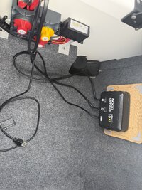
@WiskyDan wanted a way to take the charger out in the winter with the batteries. I'm not doing that, but I liked the idea of not screwing extra holes in the boat. I used some VELCRO Extreme Outdoor Double Sided Mounting Tape Holds up to 15 Pounds on Brick or Other Rough Surfaces UV and Weather Resistant Heavy Duty to stick to the carpet. I mounted the NOCO to the back of the cutting board so the rubber grips wouldn't decrease the Velcro's effectiveness. I didn't want to pry off the four rubber grips in case it would split the wood. One picture is where I mounted it and one picture is what it would look like if I mounted the Victron Shunt on the board, too, which I did not. Note, the cutting board did fall off the side bulkhead once on my last trip out. If it keeps falling, I'll leave it on the deck. The Velcro sticks really well.

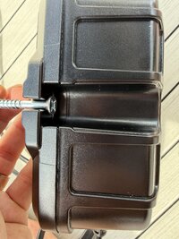
For the screws to mount, I used #Flat Phillips #10x1 to fit into the NOCO. The Phillips was angled and seemed like it would fit into the NOCO better than a flat scerw (see picture). I THINK I used a 1/8" bit to start the hole, but I might have used something a little bigger. The 1" part of that screw worked great for the bamboo board, and it's also the best length if you mount it to the same bulkhead that the battery switches are on - at least from the measurements I took.

The DVSR was more difficult for me. I used the BEP DIGITAL VOLTAGE SENSITIVE RELAY User Manual from @FSH 210 Sport. There are other options you can find if you scroll up in this thread, including an option where you don't have to pull the DVSR from the panel. See @qwikkotatx's posts above. That involves adding a switch that you will need to turn on and off.

The way I did it, if batteries are on, the DVSR will parallel the batteries when one battery is above 13.4V when the House battery is on (which it will be when you're on the boat underway with the Alternator charging the batteries). When the House battery is off (plugged into the wall at the marina), then the batteries won't be put in parallel.

I took pictures of everything, then fully unplugged all batteries. Black connections off then red. Both batteries. That might have been overkill, but I did it anyway. When you hook them back up, red on first, then black. I also had to take off one connection that connected to the top of the Battery Switch by unscrewing a nut on the forward bulkhead of the engine compartment. If in doubt, loosen more cables, not less, to pull that battery switch panel as far out as you want. I wasted a lot of time trying to do the work with it close to the bulkhead, where I didn't have enough room. Also, be careful to not yank anything too hard. I accidentally pulled a wire from a Deutsch connection. I think it was for the bilge pump to work when the battery switches are off. I used a butt connector and heat shrinked it. I probably should solder it, but that's more than I want to take on at the moment. I'll do it or have that done eventually.

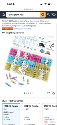
I tried to get by without a heat shrink gun by using a lighter. It worked, but I think it would have been easier in that tight space with the heat shrink gun. Based on the size of the stripper hole (that sounds dirty) I used, I believe the little pink wire to cut is 22 gauge. Follow the instructions from the link above (BEP Digital...) to know where to cut it. I left about an inch at the top part so I could fold it and heat shrink. The longer part I connected to the B screw. Strip about 1/8 to 1/4 inch of that longer red wire. Use the heat shrink (after crimping) with the ring connector appropriate for 22 gauge wires, then heat shrink.

When you put the battery switch case back on, be careful to not let that small red wire dangle down and get pinched. It did for me and I could see bare metal, so I cut that off, restripped, and reapplied a ring connection. Getting the wire in the ring connector and crimped was the most difficult part of the entire project. It was like playing Operation, but harder.

Feel free to ask if you have questions. Thank you all who helped with all my questions. Especially @FSH 210 Sport and @WiskyDan.

To test it, plug the charger in with the batteries off. At least one battery needs to be 13.4V or higher, and the red light on the bottom left of the DVSR should not illuminate (it won't illumniate below 13.4V, either). Then turn the batteries on. As long as one battery is 13.4V or greater, the red light should illuminate in about 5 seconds.

Note, the feet in the picture are not mine.

 

Attachments

  • 1779834238158.png
    1779834238158.png
    104.9 KB · Views: 4
  • Back of Battery Switch 1.jpeg
    Back of Battery Switch 1.jpeg
    2.1 MB · Views: 4
  • Back of Battery Switch 2.jpeg
    Back of Battery Switch 2.jpeg
    3.4 MB · Views: 5
  • Cutting Board with NOCO and Shunt.jpeg
    Cutting Board with NOCO and Shunt.jpeg
    2.8 MB · Views: 3
  • NOCO Placement.jpeg
    NOCO Placement.jpeg
    4.7 MB · Views: 2
  • Screws for NOCO.jpeg
    Screws for NOCO.jpeg
    2.3 MB · Views: 2
Last edited:
Why put a switch in that you need to turn on and off. The way he did it is automatic. To do the job correctly does not take that much time
Fair enough but I have to be in that area to plug in the charger anyway. The switch is no additional time and I did not have to unmount the DVSR. One of the storage mode methods in the manual mentions connecting the red wire to a switch. I am not sure if that is the ignition or a separately installed switch.
 
Went to the boat today to set up the shunt, but I got there to realize I had left the shunt at home. But while I was there, I noticed a noise I had never noticed before. But for all I know, it's always been there. When both batteries and ignition are ON, I hear a hum from the bottom of the engine compartment. When I turn the Start Battery Switch OFF, the hum goes away, and I hear a repeating click. It might be coming from the bilge pump. Something else I noticed is if the Start Battery Switch and Ignition are OFF, then I turn Ignition ON first, followed by Start Battery ON, neither the click nor the hum comes on. Does anyone know if this is normal?
Turning the House Battery OFF does not change anything.
Ignition ON with battery switches OFF, no clicking or hum.
Here is a link to a video I took where you can hear it.
I'm a little concerned that some of the electrical work I've done has messed something up.
 
Sounds like the ETV or electronic throttle valve. I hear that occasionally on my boat and it stops after a bit.

So, do you have a key start switch or push button start? Does the sound continue with the key switch off? If so does it shut off after a bit?
 
Sounds like the ETV or electronic throttle valve. I hear that occasionally on my boat and it stops after a bit.

So, do you have a key start switch or push button start? Does the sound continue with the key switch off? If so does it shut off after a bit?
I have a key to turn on the ignition. But push to start engines.
I tried to note all combinations, but I missed that one. I think I was getting nothing with ignition key off but batt switches on, but I need to double-check.
I know with ignition key on and batts off, I was getting nothing.
When you say, "sounds like the ETV," do you mean you watched the video and actually heard it? Or it sounds like it from what I wrote?
I didn't leave it on much more than a minute, and it didn't stop in that time. I'll leave it on longer the next time I am out there.
 
Last edited:
I have a key to turn on the ignition. But push to start engines.
I tried to note all combinations, but I missed that one. I think I was getting nothing with ignition key off but batt switches on, but I need to double-check.
I know with ignition key on and batts off, I was getting nothing.
When you say, "sounds like the ETV," do you mean you watched the video and actually heard it? Or it sounds like it from what I wrote?
I didn't leave it on much more than a minute, and it didn't stop in that time. I'll leave it on longer the next time I am out there.
I watched your video I’d and could hear it.

I’ll see if I can duplicate it on my boat. I think mine makes that noise for a bit after I turn the engines off. We have different power plants but I’d imagine the general engine strategies are the same.
 
Today I went back to check it out. I turned the key off and don't hear the sound. I also disconnected the bilge pump and it is not that.

After I left, something "clicked," no pun intended. When the Start Battery is turned OFF, the hum goes away and I hear a constant click. That click sound was what I heard the first time I tested out my new DVSR mod. I heard a click and the red light on the BEP illuminated.
I called the marina and asked them turn switches and ignition ON, then Start Battery OFF, and they confirmed the red light lights up each time the click happens.

So, I think the hum is the DVSR. My question is, should it be humming? The Connext screen was reading in the low 12Vs for each battery, but I know that might not be accurate. It had been off the charger for less than an hour and batteries had only been turned on for around 30 minutes or less, with nothing turned on except the bilge for a few seconds. I can't confirm right now if either voltage was 13.4 or greater. Any ideas if this is normal? Why would it be clicking with the Start Battery OFF. With OFF, the DVSR should not be doing anything.

Different topic: I noticed that when I turned on my bilge pump, I did not hear anything. If there is no water for it to pump, is it normal not to hear the pump when I turn the bilge system on?
 
“charged the battery at 100 amps which is TWICE the recommended charge rate of 50 amps.”

Straight to the point but the battery shouldn’t let this happen. Listen ul standards mean crap these days. Many other ul devices still have problems. Idk if you have skin in the game here but I don’t and I’m looking from the outside as a consumer.

I’m not gonna touch that brand with a ten foot pole and I’m not gonna recommend them to anyone. If you watch any other videos and compare the quality it’s obvious. Their design and quality is dated and garbage. Times have moved on and money can be spent on better brands.
Speaking of skin in the game….

 
Back
Top